Monday, 13 April 2020

Final year project for electronic engineering

assalam o alikum!

INTRODUCTION:

                                                   before going to hovercraft i'll put some light on it about it's background , origin , how it was made and the purposes and uses of it.

  
                                          from past i have shown in my blog i wrotten before about the drone and it was a something new for me to make an implement it and make it by my self and i'm very satisfied from the work i have done it was a moment of joy for me and i enjoyed it very much.
                    but after the discovery of drone the new thing was that why can't we combine all the three medium U.A.V like we use drone in air car L.F.R on ground and Ship's in water.... so after the thinking and a lot of meetings of engineer's it was decided make an U.A.V that can travel in all the three medium's and so some new thing was made that was latter named as hovercraft..


Design: 

                                next step is how to design a hover craft because it has to travel in all the three modes so it's designing was a difficult task rather it took long time of mine to upto 6 month's to design it but i was succeeded the design was to make two duck's in two part's of the design one horizontally and other vertically.
horizontally was to lift it up and vertical was to move it forward, having a parachute hard material piece of cloth.
 design will be cleared when you watch the video.  


Fabrication: 

                        fabrication  was easy for it rather  than it's design and other work all you need was just motor's propeller ardiuno radar RC circuit.
  1. Motor's must be 23k  rpm 
  2. propeller of clockwise with feasible  length according to the body.
  3. RC circuit of it's controlling 
  4. ardiuno
  5. hurdle detector i used Sonar ultrasonic
  6. live camera.
  7. batteries for motor's lipo
  8. battery for electronic circuit 12V.


Working: 

                there are two way's to control it one is using Bluetooth module so you can use and control it from any android app.
 simply connect the ardiuno with motor's by putting it's blue wire's the signal wire in ardiuno board and other two with batteries remember for the motors you will need different battries to get a good output so the hovercraft can be operated for a longer time.
         next step is of programming which is the easiest one just connect the ardiuno board to laptop and program as simple as you can just to give command of forward and move the radar left and right for the movement of hovercraft and also implement the coding of hurdle detector.

the vedio will show it in working.
                                                        https://www.youtube.com/watch?v=DtDzSMK_sco

Uses of  hovercraft: 

  1. it's an easy and less time consuming project.
  2. A good and one of the best final year project's.
  3. It can be used in 3 modes air water and ground.  
  4. It can be used do rescue the people injured in flood or earth quick.
  5. It can be used in every that place where we can't help human's like in earth quick or flood we can use it to sent food medical equipment's.
  6. it is lighter in weight so it can fly upto 3 feet's and can cross the heavy river's or flood area and can move upto 8 person's depending on the size of hovercraft.
do support for more project's if there is any problem any question just mention it below in comment i will answer it .                              

Saturday, 26 May 2018

Ronaldinho 2015

Assalam o alikum!

                               best ever and last vedio of 

R10


Saturday, 12 May 2018

flying RC car.

Assalam o Alikum!

                                 Do you want a practical personal flyingcar? I really want it, so i made a cute monster. It's a concept model of flyingcar. Actually the monster had take off and land safely without crash,

I believe human can free flight in this century.  people can easy to dive aircraft as a car(with wheels).
If a aircraft will become a practical flying car. I think it must be have these basic feature:
1. VTOL(vertical take off and landing)
Even most rich place or country in the world, you can't build airport for every family. If a practical family aircraft always take off or landing with airport, it's really not easy to use. it can't became the public transportation.

2. All moving part must be inside shells. 
Many modern city always crowd. The flyingcar must safely fly through between high-rise. And can get some small collision without crash, not such as helicopter.

3. Technology was extreme low-end and structure was extreme simple.
Most often something was more simple means it will more cheap and safely. I hope the flyingcar is cheap, very family can buy it.

4. Fly don't  be dependent on aerodynamics, but dependent on a stupid truth: thrust > gravity.
That's really important. If a aircraft can fly without aerodynamics, means it will easy to made. Everyone can build it.

5. Long distance of flight
World's first manned flight with an electric multicopter was succeeded in Germany.  The multicopter will become practical  flyingcar. But now the battery really don't enough for Long distance's flight. So the flyingcar must can use other engine(eg: jet, piston).

I wasn't a rich guy or celebrity. So i don't have enough money to make real flying car, i just share my idea: SPOFC
If you interesting in this idea, please try make a cute model or tell other one. Let us try build real flying car by everybody.

STEP NO 1:


Picture of Concept of My Flyingcar


The air has one way in to three way out. Every gas outlet need control flow rate, so there is a 3 point made different force, it can control the flying car movement. One outlet of three can rotate, it can control the flying car's direction.
The control system come from traditional helicopter CCPM system, but not exactly same, need do some fix. You can found more detail in step 10 and 11.


Step 2: Prepare Material for Flying Car

Picture of Prepare Material for Flying Car

1. downloading cad file and use plywood of thickness was 2mm to laser cut.
2. radio system, number of channel was at least 5.
3. Hex nylon standoffs:
       m3*10.......x 8
       m4*25.......x 4
4. Nylon screw
       m3*8........x 12
       m4*12.......x 12
5. Hex nylon nut
       m3........x 8
       m4........x 12
6. steel screw m2*12 x 8
7. ESC: Platinum-60A-PRO x 1
8. motor: DUALSKY 3548ca-5 850kv x 1 (not recommend, The reason in the following)
9. controller/autopilot: APM2 or MWC(MWC is best)
10. propellers: gws 1045 3-blade x 1
11. battery: 6S 1300mAh x 1
12. servo: springRC SM-S3481M x 3, SM-S3471M x 1
13. epoxy glue, recommend prepare a glue gun
14. Flange bearings 4*7*2.5 x 4

About motor: the 3548ca-5 850kv can't work in 6s cell. I ignore this bug in project beginning, so my all design keep this trouble. Now I no time and money to find new motor and propeller, make whole new design. They need make about 4kg thrust, it's not easy found. But fortunately i have four 3548ca-5 850kv, Now three motor let me go on test flying. Maybe your can found other engine to make it.

Step 3: Reference for the FramePicture of Reference for the Frame

Step 4: Air Valve

Picture of Air ValvePicture of Air ValvePicture of Air Valve

Step 5: Build Body

Picture of Build BodyPicture of Build Body

Step 6: First Put All Air Valve Into Frame, Then Close It

Picture of First Put  All Air Valve Into Frame, Then Close It.Picture of First Put  All Air Valve Into Frame, Then Close It.Picture of First Put  All Air Valve Into Frame, Then Close It.

Step 7: Wait One Night for Glue Become Most Strong

Picture of Wait One Night for Glue Become Most Strong

Step 8: Assemble Servos and Valve's Position Hit

Picture of Assemble Servos and Valve's Position HitPicture of Assemble Servos and Valve's Position Hit

Step 9: Put Motor and ESC Into Frame

Picture of Put Motor and ESC Into FramePicture of Put Motor and ESC Into Frame

Picture of Put Motor and ESC Into Frame

Step 10: Control System

Picture of Control System

Picture of Control System

We can image Helicopter was 3 point: left, right, rear. Power of these point sometime change smaller, sometime change bigger. But My flyingcar always smaller.

Tuesday, 1 May 2018

how to make robot

Assalam o alikum!💐
   

how to make robot:

before starting i wanna inform you that what is a robot, by defination 

machine capable of carrying out a complex series of actions automatically, especially one programmable by a computer .

making robot from cardboard :


 for this purpose you need cardboard sheet's. 
  1.  dc motor's with gear having atleast 150RPM.
  2.  big tyre of toy car.
  3. glue gun.
  4. momentry contact push button's.
  5. wire's
batteries of 9V.

for the detail of making see this vedio it will show you every thing step by step.


Monday, 26 March 2018

circuit diagram's and coding of line following robot.

Assalam o alikum!
                           
                          this article will show code and circuit diagram of l.f.r

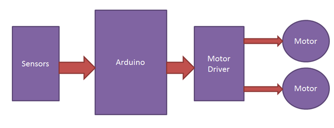
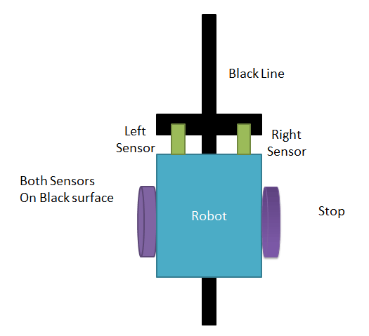
1)                                this diagram show's how l.f.r work's


Working of Line Follower Robot using Arduino

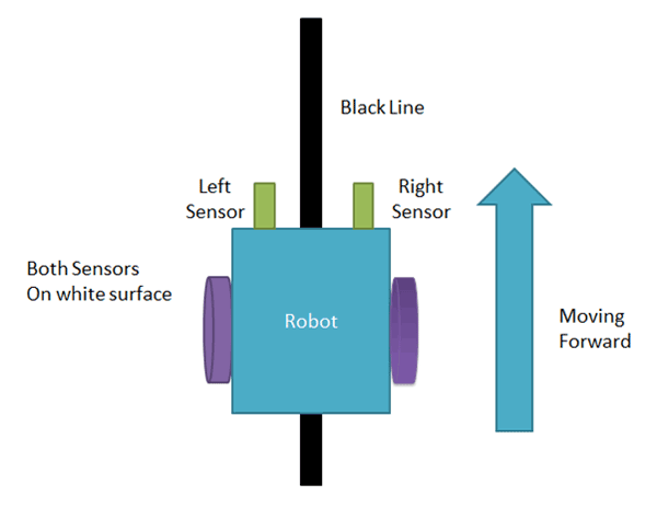
2)              when lfr is on track (following black line).

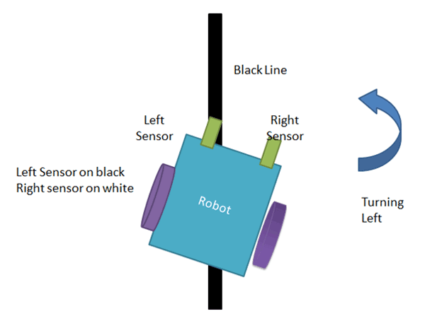
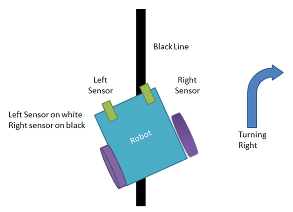
moving forward,left,right and stoping.

Working of Arduino Line Follower Robot
Turning left to line follower robot using arduino


Turning right to line follower robot

Stopping Arduino Line Following Robot

circuit diagram


---------x-------x-----x------x------x-------x------x------x------x------x-----x-----x------x-----x----x----------

CODE


/*------ Arduino Line Follower Code----- */
/*-------definning Inputs------*/
#define LS 2      // left sensor
#define RS 3      // right sensor
/*-------definning Outputs------*/
#define LM1 4       // left motor
#define LM2 5       // left motor
#define RM1 6       // right motor
#define RM2 7       // right motor
void setup()
{
  pinMode(LS, INPUT);
  pinMode(RS, INPUT);
  pinMode(LM1, OUTPUT);
  pinMode(LM2, OUTPUT);
  pinMode(RM1, OUTPUT);
  pinMode(RM2, OUTPUT);
}
void loop()
{
  if(digitalRead(LS) && digitalRead(RS))     // Move Forward
  {
    digitalWrite(LM1, HIGH);
    digitalWrite(LM2, LOW);
    digitalWrite(RM1, HIGH);
    digitalWrite(RM2, LOW);
  }

  if(!(digitalRead(LS)) && digitalRead(RS))     // Turn right
  {
    digitalWrite(LM1, LOW);
    digitalWrite(LM2, LOW);
    digitalWrite(RM1, HIGH);
    digitalWrite(RM2, LOW);
  }

  if(digitalRead(LS) && !(digitalRead(RS)))     // turn left
  {
    digitalWrite(LM1, HIGH);
    digitalWrite(LM2, LOW);
    digitalWrite(RM1, LOW);
    digitalWrite(RM2, LOW);
  }

  if(!(digitalRead(LS)) && !(digitalRead(RS)))     // stop
  {
    digitalWrite(LM1, LOW);
    digitalWrite(LM2, LOW);
    digitalWrite(RM1, LOW);
    digitalWrite(RM2, LOW);
  }
}


Friday, 16 March 2018

line following robot by using ardiuno 'uno'

Assalam o Alikum!


Line Following Robot (L.f.R)


it's a simple car that follow's the line for moving from one place to another. hence it's called line following robot.

it's uses several component's of electronics for becoming LFR.

Component's:

 LFR uses
  1. Body.
  2. motor's.
  3. gear system (if motor's are dc).
  4. Ardiuno (uno). 
  5. motor drive.
  6. battery.
  7. jumper wire's
  8. sensor's. 

Description of component's.

Body:

  for body it's must that it should be good looking and lieghtr in weight bcz it has to move fast and bear load on it to0.

Motor:

motor's doen't mean that u use heavier one u can simply use a dc motor with gear system running on 7 or 12 volt's but it's torque should be greater then 100. bcz rpm doesn't matter that much as torque matter's.

Ardiuno:

 it's a controller that will give instruction's and the motor's would be driven by motor drive

Sensor's:

if you wanna win the lap and even the contest too your sensor's should be good enough.


How to assemble it:

the final stage will show you vedio how to do it's assmbling.


Friday, 9 March 2018

PID controller controlling speed of a dc motor.

THE PID CONTROLLER:
The term PID is an acronym that stands for Proportional Integral Derivative. A PID controller is part of a feedback system. A PID system uses Proportional, Integral, and Derivative drive elements to control a process. Some of you already know what P, I, and D stand for. Don’t worry if you don’t; we will soon cover these terms with easy-to-understand examples.
Why Do I Need PID Control?
You need the PID because there are some things that are difficult to control using standard methods. Let me illustrate with an example. My first experience with control systems was a failure. My goal was to regulate the output of a power supply using a PIC microcontroller. The PIC read the output voltage with an AD converter and adjusted a PWM to regulate the output. The control strategy was very simple: If the voltage was below a set-point, turn on the PWM. If the measured voltage was above the set-point, then turn off the PWM. The PIC power supply almost worked. It did produce the DC output voltage that I wanted. Unfortunately, it also has a significant AC ripple riding on the DC signal.

What Is Integral?

Integral is shorthand for integration. You can think of this as accumulation (adding) of a quantity over time. For example, you are now integrating this information into your store of knowledge. Your store of knowledge has components of both time and knowledge. Obviously, we all started as babies with virtually no knowledge. Over time, we have integrated knowledge into our brains.
In our PID controller, we are integrating voltage as time progresses. A schematic of an integrator circuit is shown in Figure:


What Is Derivative?

The derivative is a measurement of the rate of change. The ideal differentiator is shown in Figure. This circuit looks similar to the high pass filters you have seen in other schematics. Low frequencies are attenuated, while high frequencies are allowed to pass. The mathematics that describes the differentiator is:
Vout = -RC * (rate of change)
Rate of change is equivalent to measuring the slope of a line. Slope is a measure of the change in voltage divided by the change in time. In mathematical terms, this is referred to as a delta voltage over delta time or simply dv/dt. If we apply a ramp to the differentiator, we get a steady DC output voltage. Figureillustrates the input/output relationship of a differentiator.


Servo Motor System:

Now that we are familiar with the P, I, and D terms, let’s examine how they are combined to form a complete system. We will be using the PID controller to control a DC servo motor. I used a Hitec brand servo motor typically found in R/C model cars and airplanes. This servo is inexpensive and readily available. You can also purchase replacement gears — more of that in the next installment.


PID Block Diagram:

A block diagram showing the functional relationships of the PID controller is shown in figure.


CIRCUIT DIAGRAM:


CIRCUIT DESCRIPTION:
This schematic is an adaptation of the PID controller presented by Professor Jacob in his book, Industrial Control Electronics. This type of system has the advantage of easy tuning. This circuit is also simple and easy to construct.
The schematic has the same physical layout as the block diagram. Op-amp U1 is used as the summing junction for the set-point and measured motor position. The individual P, I, and D functions are implemented by U2, U3, and U4, respectively. Finally, op-amp U5 sums the individual PID terms. The P and I terms are inverted, while the D term is not. Darlington transistors have been added to U5 to boost the current to a level sufficient to drive the motor.
The individual P, I, and D components appear just as they were presented earlier in this article. Each of the terms has a variable resistor to adjust its gains. The adjustment (tuning) of this circuit is the topic for the next installment.
Component selection for this circuit is not critical. The variable resistors should be multiturn for ease of adjustment. General-purpose op-amps may be used; however, U3 should be a FET input type. The FET design is better for the integrator, since it will not self-charge the integrator capacitor. I found a quad op-amp — such as the LF347N — to be ideal for this application. Large capacitors are required for the integrator and derivative circuits. The large values necessitate that electrolytic capacitors be used. The electrolytic capacitor may be operated as a non-polarized capacitor by placing two capacitors in series, as shown in the schematic.

Final year project for electronic engineering

assalam o alikum! INTRODUCTION:                                                    before going to hovercraft i'll put some light o...